Apr 1, 2021
The closed die forging process can generate several types of defects that will impact the quality of your part. FORGE®, simulation software for hot forming processes, eliminates trial and error to produce a compliant part (in terms of final geometry and without defects) and achievable the first time. The simulation allows you to detect manufacturing defects; it is a reliable solution for reducing production costs and non-quality costs by ensuring components meet specifications and avoiding production machine downtime.
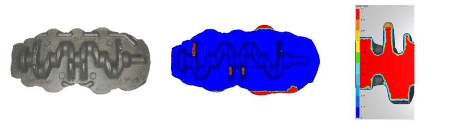
Predict underfill areas
An underfill defect occurs when the metal flow has not completely filled a section of the die cavity. It is caused primarily by a lack of material or imperfect die design, or even by an inappropriate forging technique.
Its origin can be determined thanks to the digital simulation and thus, solutions can be found to avoid the appearance of this defect on your real part.
To identify underfill areas with FORGE®, the “Contact” scalar can be selected from the list of results. The underfill areas will then be highlighted in red (areas where the scalar has a positive value) at the end of the manufacturing step.
Detect material folds
This type of defect appears when two parts of the material fold against each other. Once more, this phenomenon can be caused by a lack of material, poor die design, or a poorly controlled process.
Simulation can help anticipate this defect. In FORGE®, a point tracking feature is available to easily detect the appearance of folds in the part. It is used to:
- Identify cold-shuts at each stage of forging
- Follow the folds and determine whether they remain in the part or whether they move towards the flash
- Measure the depth of a fold
- Perform a reverse analysis to determine the origin of the fold
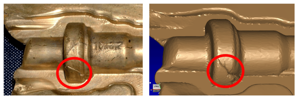
Point tracking can be enabled from the toolbar, "Folds" tab to view the folds in the graphic view. Points in red indicate areas where the material comes into contact with itself.
FORGE® automatic remeshing brings precision to the location, size and depth of folds.
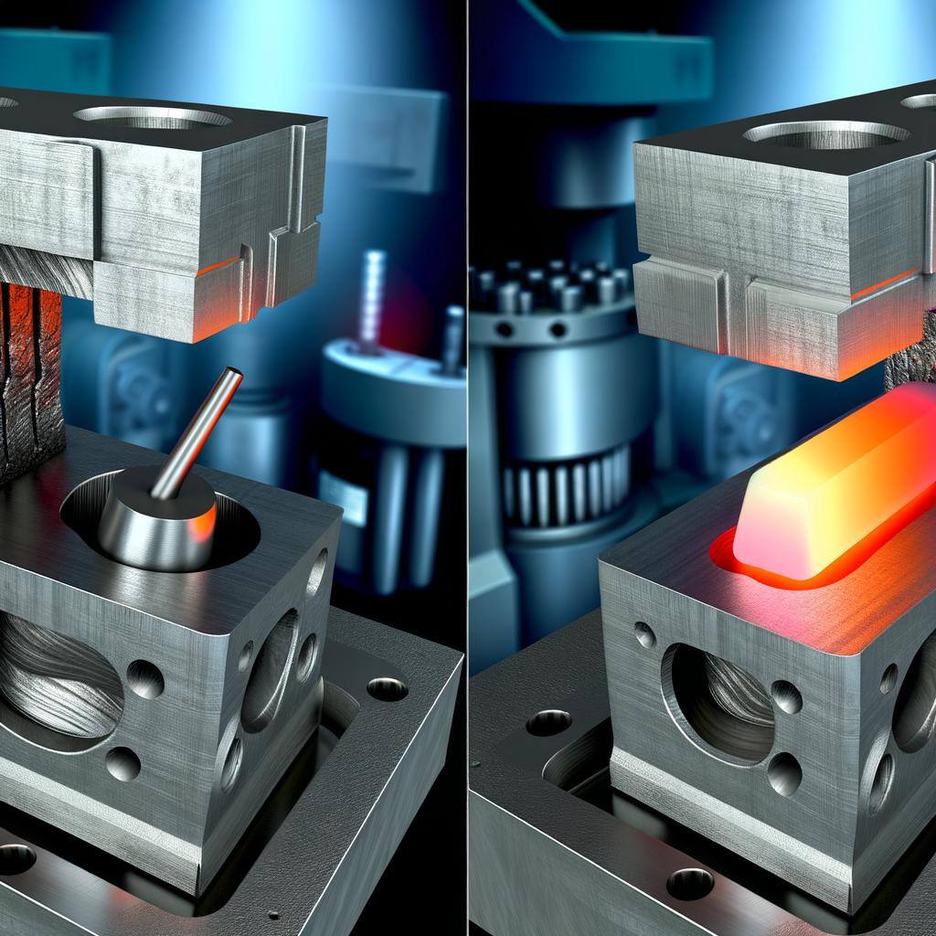
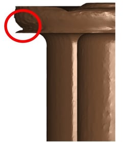
Anticipate piping defects
Piping defects appear mainly at the end of the forging step. Flow competition then occurs between areas where the material is blocked (completely filled area) and adjacent areas where the material continues to flow, thus creating this piping phenomenon. This defect is particularly tricky because it cannot be detected on the surface of the part (this is known as an under-skin defect) and it requires non-destructive testing (e.g.: ultrasound) to highlight the critical areas. Typically, this type of defect may occur in extrusion processes where the flow of material combines forward extrusion and backward extrusion. The defect can generally be eliminated by rethinking the forging process and modifying certain dimensions (extrusion diameter, angle, connecting radius, etc.)
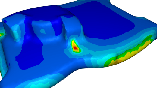
By simulating this process with FORGE®, piping defects can be detected thanks to the under-skin marking feature.
In these cases of extrusion, two piping defects could be identified by under-skin marking: one on the top surface, and the other in the corner. In these areas, the material flow velocity is close to zero.
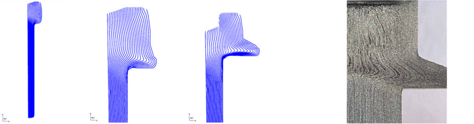
Predict fibering defects
When a part is forged, metal deformation changes the orientation of the fibering. The fibering lines may not be oriented in the desired direction or may not meet specific needs to ensure the mechanical quality of the part.
Numerical simulation makes it possible to model a part's fibering. The FORGE® marking grid feature allows you to calculate changes in fibering and to judge its quality throughout the deformation range. Final fibering compliance will be a guarantee of the quality of the forged part.
The following example (courtesy to the Miguel Altuna Institute, Spain) shows changes in fibering over a complete cold forming process. With each pass, the part deforms more and the fibering changes.
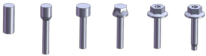
The marking calculation carried out by the FORGE® software shows on the final form that fibering complies with the SAE USCAR8 specification.
Avoid cracks
Cracks may appear on the surface or in the mass of a forged part. They are usually caused by billet stretching when the deformation is too sudden. The quality of the initial billet (defects linked to the foundry process: porosities, segregations, etc.) is also called into question since a force applied to a part exhibiting a defect can cause a crack.
The appearance of cracks can easily be anticipated using finite element simulation. The FORGE® software models the deformation and flow of the metal based on your process parameters, allowing the behavior of the flow to be analyzed throughout forging. It incorporates several damage criteria to anticipate these cracks: some of them are coupled with rheology such as Lemaitre and others are uncoupled Oyane, Rice & Tracey, Latham & Cockroft, Brozzo, Hill-Devaux, Ghosh, Ayada, Lemaitre 1, 2, 3, 4, 5.
The origin of a crack can be found using FORGE®: location of the area where the defect was initially formed and how it evolved to create a crack. The size, depth and propagation of the crack can also be modeled.
FORGE® software also makes it possible to avoid defects linked to other forming processes such as extrusion, ring rolling, cross-wedge rolling, etc.